| Ⅰ. Overview |
| Able to accurately simulate a wide range of complicated natural environments, and is suitable for reliability test in industrial products. Meet GB5170.2.3.5.6-95 standard requirements of environmental testing equipment and test methods for the basic parameters of electric and electronic products under the condition of humidity, low temperature, high temperature, and constant heat. |
| Ⅱ. Application |
| Walk in Climatic chamber is intended for thermal and humidity testing of construction materials, objects and structures, investigation and development of high-efficiency energy-saving durable materials, objects and structures. |
| Ⅲ. Features |
|
● GB-2423.1-89(IEC68-2-1) Test A: Low Temperature Test
● GB-2423.2-89(IEC68-2-2) Test B: High Temperature Test
● GJB360.8-87(MIL-STD.202F) High Temperature Operating Life Test
● GBJl50.3(MIL-STD-810D) High Temperature Test
● GJBl50.4(MIL-STD-810D) Low Temperature Test
● GB2423.3-93(IEC68-2-3) Test Ca: method for steady-state damp heat test
● GB2423.4-93(IEC68-2—30) Test Db: Damp Heat Alternative Test.
● GJBl50.9-93(MIL-STD-810D) Damp Heat Test
|
|
Energy Conservation
|
Bypass mode to adjust cooling capacity to achieve a constant temperature and humidity effectively |
| user-friendly control |
※KOMEG Programmable KM-3166 LCD Touch Screen Controller with PID control parameters setting
※RO Water Purifier automatically supplement humidifying water;
※Flexible approach for data collection and recording
|
|
High reliability
|
※Key Parts are imported to ensure the service life and high reliability;
※High efficient oil separator to ensure the service life of compressor;
※Using R.O. Water Purifier to ensure long service life.
|
| Ⅳ. Main Technical Index |
- Chamber body
|
| 1.1 Workplace Volume |
IW 3000 × IH 2100 × ID 2000 mm
Inner Volume:about 12.6m3
|
| 1.2 External Size |
according to the final design |
- Temperature
|
| 2.1 Temp. Range |
-30℃ ~ +80℃ |
| 2.2 Temp. Deviation |
±2.0℃ |
| 2.3 Temp. Fluctuation |
±0.5℃ |
| 2.4 Temp. Uniformity |
±2.0℃ |
| 2.5 Temp Accuracy |
±1.0℃ |
| 2.6 Heating & Cooling Rate |
RT ↓ -30℃ within 90min (no load, ambient temperature is 25℃)
RT ↑ +80℃ within 80min (no load, ambient temperature is 25℃)
|
- Humidity
|
| 3.1 Humidity Range |
10%-98%RH |
| 3.2 Humidity Deviation |
±2.0%RH(>75%RH)
±5.0%RH(≤75%RH)
|
| 3.3 Humidity Uniformity |
±5.0%RH |
| 3.4 Humidity Fluctuation |
±2.0%RH |
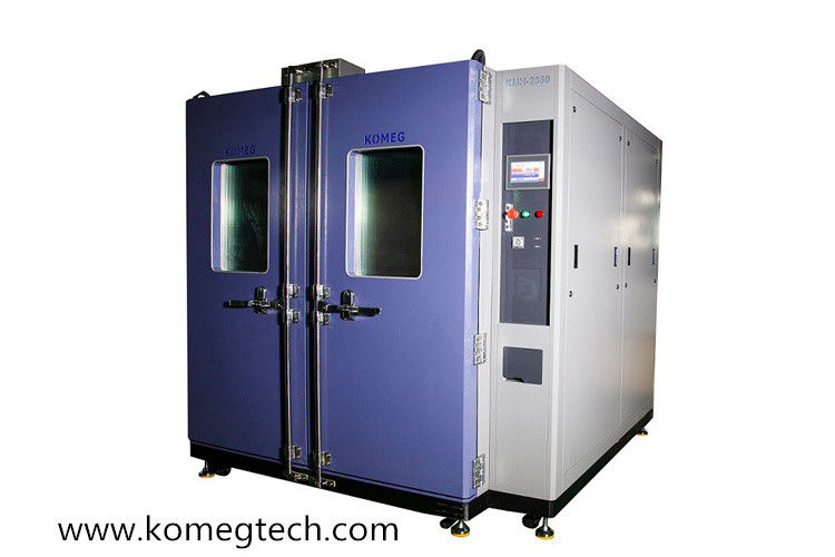
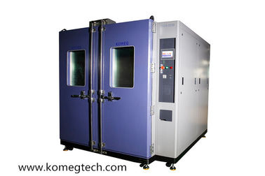
| Ⅴ. Body Structure |
| Overall structure and chamber consists of three parts: Insulation box, separate refrigeration unit, and electric control cabinet. |
| Insulation Body |
※Out Wall Material: high-quality carbon steel plate with static color spray
※Internal Shell Material: SUS304# honed stainless steel plate
※Insulation Material: glass wool + rigid polyurethane foam insulation layer
|
|
Door
|
Double doors, with heating wires installed around the door frame to prevent door frame condensation when at low temperatures |
|
Inspection Window
|
Transparent electro thermal coated hollow toughened glass *2 (located on the door)
Visibility Scope: about W460mm×H560mm; including the lamp shadow scope
Multi-hollow electric insulation coated glass prevent condensation effectively
|
|
Portholes
|
φ50mm *2, located on the left of the body with rubber stopper and plastic cover |
|
Lighting Device
|
11W/AC220V 1 installed on inspection window |
|
Condensate Outlet Holes
|
Available for workplace box and refrigeration unit |
|
Samples Holder
|
Two layers of Stainless Steel Samples Holder
load bearing (uniform distribution) 50KG/ layer
|
|
Mobile Castors
|
Mobile Castors*4 , equipped with feet cup |
|
Switch Gear
|
Total power supply circuit breaker, over-temperature protection |
|
Water Supply System
|
Water Pump automatically supply water |
|
Power consumption
|
To be advised |
|
Weight
|
About 25000KG(subject to actual weight) |
| Ⅵ. Air Conditioning System |
|
Control Mode
|
Forced ventilation loops design, Balanced Temperature & Humidity Control System (BTHC)
|
|
Air Conditioning Device
|
Top-mounted air diffuser to ensure inside uniformity of temperature and humidity et
Long axis centrifugal fan, evaporators, heaters, humidifiers was installed on air conditioning box
|
|
Heating up
|
Quality nickel-chromium alloy wire electric heaters,
Non-contact control mode(SRR)
|
|
Cooling down
|
Sine wave pattern aluminum finned copper tube air heat exchange (air-cooled ) |
|
Water Supply
|
Inner water supply system(damp-heat type) |
|
Humidifying (damp-heat type)
|
Basin heated humidification
Stainless steel sheathed heater
Heater control: non-contact period, such as pulse width modulation, SSR(Solid State Relay)
Water level control devices, anti-dry unit heater
|
|
Compressor
|
France Tecumseh Compressor |
|
Throttling Device
|
Thermal expansion valve & capillary
|
|
Refrigerant
|
Environmental friendly high-temperature level refrigerant: R404a |
|
Part Brand
|
| Parts |
Brand |
Remarks |
| Compressor |
Tecumseh |
Hermetic piston compressor with low noise |
| Oil Separator |
ALCO, AC&R, ESK |
|
| Evaporator condenser (plate heat exchanger) |
DANFOSS |
|
| Pressure Relay |
DANFOSS
RANCO
|
|
| Condenser (Plate) |
DANFOSS |
|
| Condenser |
Yongqiang |
|
| Drying Screen Program |
DANFOSS
SPORLAN
|
|
| Capillary |
KOMEG |
|
| Expansion Valve |
DANFOSS, SPORLAN |
|
| Electromagnetic Valve |
SAGINOMIYA &
CASTEL
|
|
| Exhaust Gas Pressure Regulating valve |
SAGINOMIYA |
|
| Condensing Pressure Regulating Valve |
SAGINOMIYA DANFOSS |
|
| Note: Two options listed is for alternate choice and backup purpose |
|
| Refrigerating technology |
※Nitrogen welding, two-stage rotary vane vacuum pump, ensure that the internal cooling system clean and reliable
※water tray located at the bottom of the compressor to ensure condensate water drain through pipe freely at the rear of the chamber.
|
| Ⅶ. Control System |
| 1.Curve Recording Function |
Pt100 Platinum Resistance |
| 2.Controller |
KOMEG Programmable KM-3166 LCD Touch Screen Controller with PID control parameters setting
|
| 3.Display Function |
Temperature and humidity settings (SV) Practical (PV) value can be displayed directly,
Execution of the program can display numbers, paragraphs, remaining time and cycles, running time display,
Program editing and graphic curve display,
Fixed or program operation status display,
7-inch TFT display screen.
|
| 4.Display Resolution |
Temperature: + 0.01℃; Humidity: + 0.1%; time: 1sed. |
| 5.Setting Range |
Temperature can be adjusted based on the working temp. range of the equipment (the upper limit: +5℃, the lower limit : -5℃) |
| 6.Operation Mode |
Programmable running, constant running and booking boot |
| 7.Setting Mode |
Touch Mode Input |
| 8.Communication Interface |
Data collection and curve display when connected to a computer
Can be used as monitoring and remote control system
Multiple machines synchronization control available
|
| 9.U Disk Memory Card |
1G-8G available for downloading historical curve, data, pluggable |
| 10.Data Collection |
RAM with battery protection, setting(SV), Practical(PV) and sampling time can be saved;
Maximum historical data memory storage is 90 days (when the sampling time is 1 min)
|
| 11.Power Off Memory Function |
Power recovery mode can be set as hot start, cold start and stop |
| 12.Pre-set Function |
Boot time can be set freely and machine runs automatically when turning on power |
| 13.Software Environment |
Windows 2000 or Windows XP |
| 14.Network Connection |
Can be connected to Ethernet via professional software, remote control & assistance function and data collection can be achieved through network, , multiple machine can be controlled simultaneously |
| 15.Accessory(Standard configuration) |
Fault alarm and cause handling prompts, power failure protection, the temperature upper and lower limit protection, timer function (automatic start and automatic stop running) |
| Ⅷ. Electrical Apparatus Control System |
| 1. Switch Gear |
※Cooling fan;
※Switch board;
※Specimens terminal;
※RS-485 physical interface( if purchase centralized monitoring software);
※Total Power Supply Leakage Breaker.
|
|
2. Part Brand
|
| Parts |
Brand |
Remarks |
| Controller |
KOMEG |
KM-3166 LCD
touch screen
|
| Circuit Breaker |
Schneider |
|
| AC Contactor |
Fuji, Schneider |
|
| Thermal Relay |
Schneider |
|
| Phase Sequence Relay |
Carlo Gavazzi |
|
| Time Relay |
Autonics, OMRON |
|
| AC Relay |
Schneider |
|
| Solid State Relay |
Carlo Gavazzi |
|
| Temperature Fuse |
Emerson, MICROTEMP |
|
|
Note: two options listed above is for customers alternate choice and
backup purpose
|
|
| 3. Protection System |
3.1 Refrigeration System:
※Compressor overpressure protection;
※Compressor motor overheating protection;
※Compressor motor over-current protection;
※Cooling fan overheating protection.
3.2 Laboratory
※Adjustable over-temperature protection
---over-temperature protection mode 1;
※Test space temperature fuse
--- over-temperature protection mode 2;
※Air conditioning channel limit over-temperature
--- over-temperature protection mode 3
※Controller set over-temperature shutdown alarm
--- over-temperature protection mode 4
※Fan motor over-heating
3.3 Other
※The total power phase sequence and phase loss protection
※leakage protection;
※Overload and short-circuit protection.
|
- Alarm Indication
|
Equipment stops running and sends audible alarm when the above protection appears, meanwhile, fault, causes and solutions will be displayed on the screen. |
| Ⅸ. Installation Environment |
|
- Power
|
※AC380V±10%, 50Hz±1Hz, 3 phase 4 wires+ Ground Wires;
※Power cable is connected to the air switch in control box
※Total Power: 17 kW; 32A;
※Volta Permitted: AC(1±10%)380V ;
※Sequence Permitted:(1±1%)50Hz;
※Resistance of ground wire is less than4Ω;
TN-S or TT mode for power supply;
※Must be equipped with air or power switch used by this device only
|
| 2. Water Supply |
※Humidification Water: purified or deionized water; Maximum Water Volume: subject to actual consumption;
※When using RO Water Purifier, water supply requirements are:
Water Pressure: 0.2MPa; pipe line: DN10; Flow Quantity & Maximum Water Volume: subject to actual situation
|
| 3.Surrounding Environment |
5 ~ 35℃, Relative Humidity ≤85%R.H; Atmospheric Pressure: 86kPa~106kPa. |
| 4. Air Quality |
No high concentrations of dust or corrosive gases |
| 5. Installation Place Requirements |
※Distance from the wall to both sides and rear of chamber more than 800mm, to the front more than 1500mm. Provide independent distribution switchgear, humidification condensate drains, and external power connector device is necessary.
※Ground level, well-ventilated, no flammable, explosive, corrosive gases and dust;
※No strong electromagnetic radiation nearby;
※With floor drain(less than 2 meters from the refrigeration unit);
※Venus Floor load capacity: not less than 800kg/ m2;
※Leave adequate space for maintenance
|
| 6. Ground Connection |
Grounding resistance less than 4Ω, grounding bolts located at the base of the cabinet |
- Water Draining
|
Drain hole located at the base of cabinet |
- Fairlead
|
φ50,φ80,φ100,φ120mmcable port, location and number can be customized according to user requirements if chamber body structure allows |
| 9. Equipment Storage |
※When the device does not work, the ambient temperature should be maintained within 0~45℃;
※When the ambient temperature is below 0℃, the water remaining in the device should be drained out to avoid water pipes freezing and broken.
|
| 10. Centralized Monitoring |
For remote centralized monitoring, need another PC (Windows 2000/XP operating system, a COM port and a USB port). |
| Ⅹ. Technical Documentation |
| 1. Technical Documentation |
※Product certificate*1
※Operational Manual*1
※Maintenance Manual*1
※Circuit diagram: one copy;
|
 Your message must be between 20-3,000 characters!